Project VOLT
This post is the build log of my stationary computer, “Project VOLT”. Most of the text and images are derived from a thread over at Overclockers forum that I originally posted during the build process in the summer of 2011. I will copypaste it here in its entirety and mark my corrections/additions in red text. I will go through the text once, correct/critique as I go along, and post it. The text will be treated it as if it was written by someone else (which, in a way it is). I’m curious to see how much I have learned in the past 3.5 years. The computer specs may start to feel a bit outdated, but the ATX form factor won’t go anywhere soon (I hope).
Update 0: Background
originally posted 2011-06-25
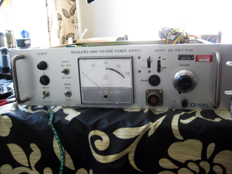
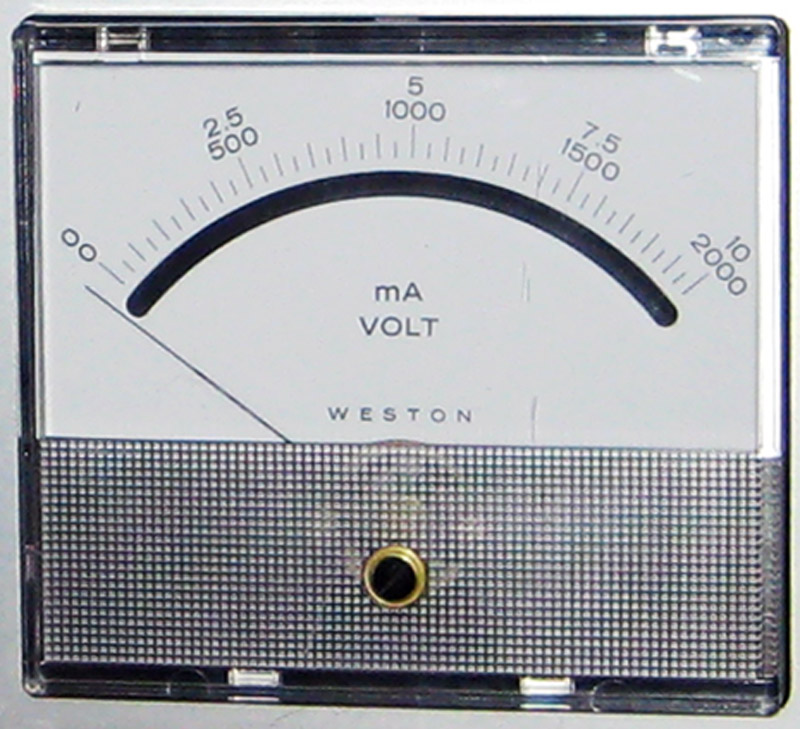
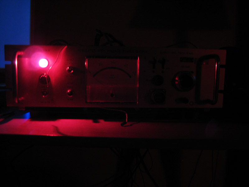
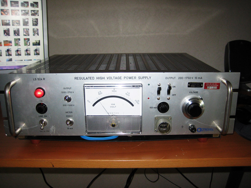
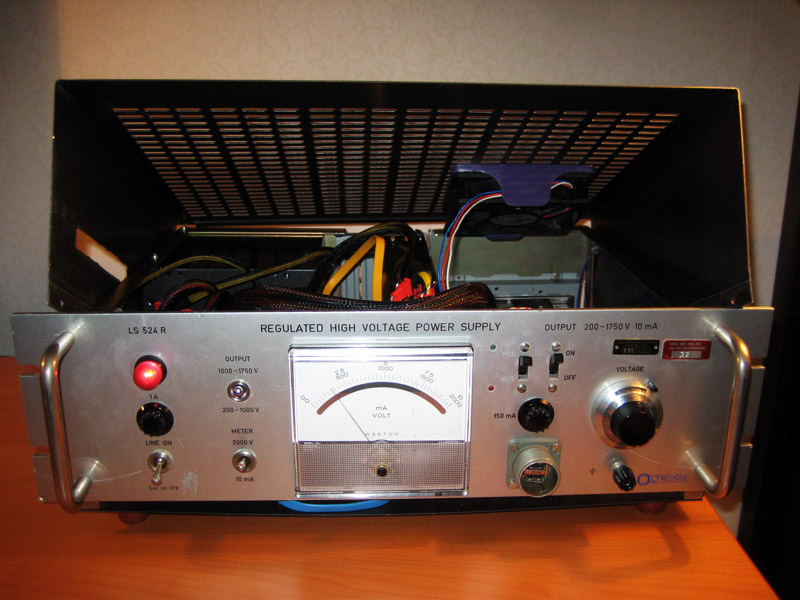
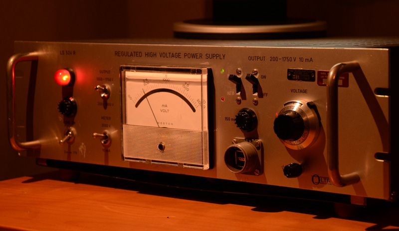
Working as a researcher in Life Science, I frequently notice beautiful old science equipment getting tossed out of department storage rooms. One day, I found this gem in the electronics recycling room, a regulated analogue high voltage power supply from 1964!
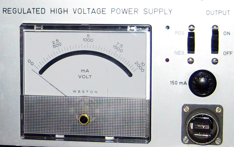
Front panel:
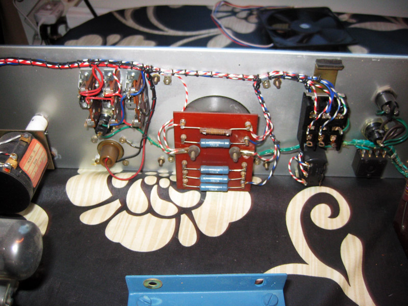
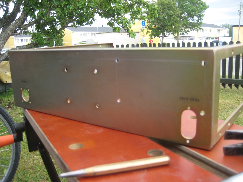
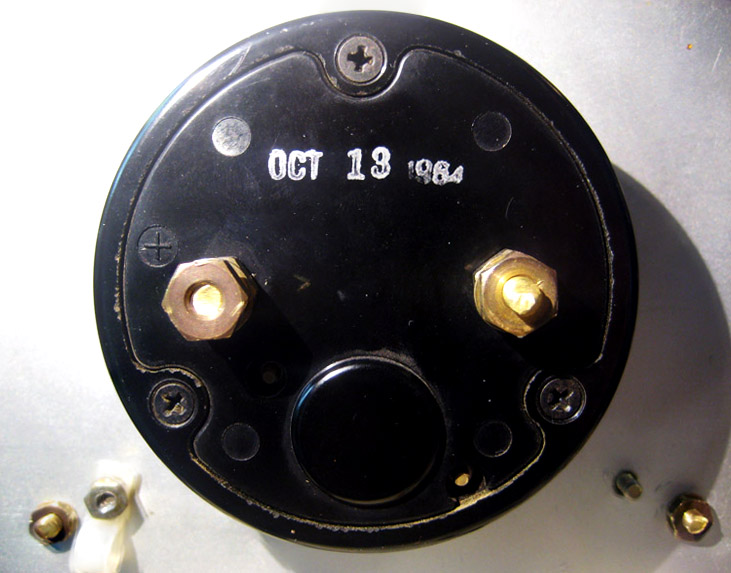
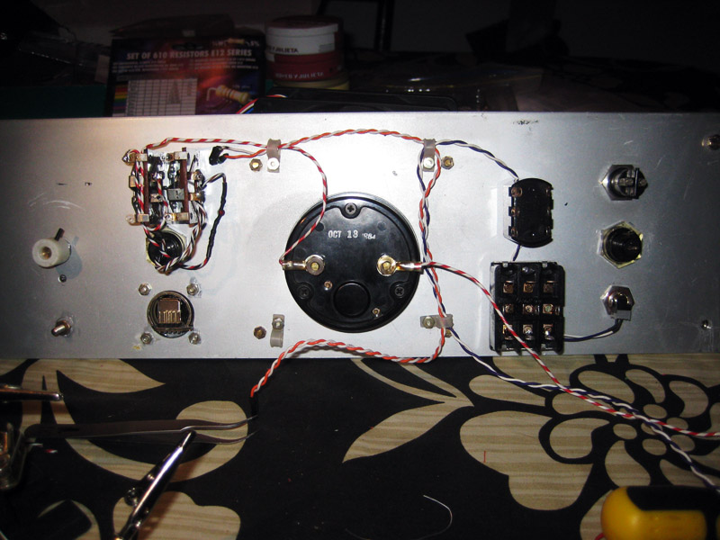
Back side of front panel:
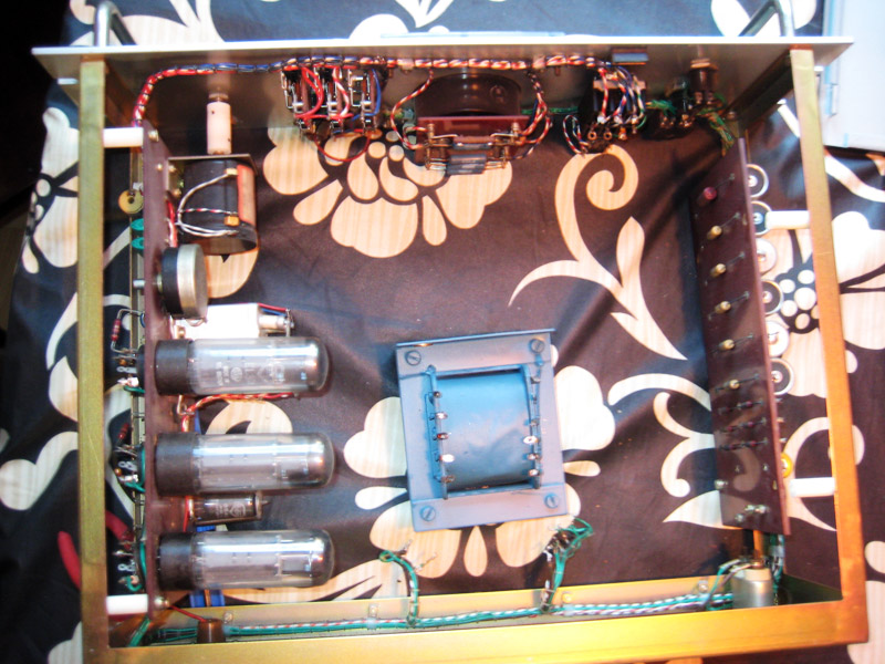
Guts view from top. I had already desoldered the transformer coil housing when taking the picture.
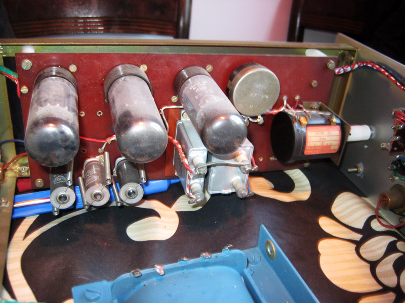
Tubes and potentiometer that are going to be recycled into a tube amp in the future. I never got around to doing that. The tubes and the beefy potentiometer were thrown out during my move from Uppsala to Oslo.
Now my plan is to strip its guts and fill it with my new computer:
- CPU: i5 2500K
- MB: GA-Z68MX-UD2H-B3
- RAM: 4x4GB Corsair XMS3 1600 MHz
- GPU: ATI RADEON EAH6870 DC/2DI2S/1GD5
- HDD: OCZ Agility 3 120 GB SSD
- Storage: 2X2TB Samsung EcoGreen F4, RAID 1
- Blue-ray: Lite-on 12X
- PSU: OCZ ModXstream Pro 600W
All whilst retaining the functionality of as may of the front panel buttons and meters as possible. ‘Whilst’, seriously? What’s wrong with ‘while’? Don’t be silly and pompous!
The pictures are not sharp and should at minimum be cropped straight. Additionally, you should fix the exposure & white balance in them. They look sloppy, where is your sense of aesthetics?
Update 1: The Plan
originally posted 2011-06-25
I wish to retain the original warm analogue lamp as the system indicator light, there are way too many LEDs in case modding anyway. My plan is to have all the old components mimic their original function in some form or other as closely as possible.
For the first circuit I designed this simple diagram (see first post for pics of original look):
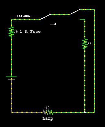
As you can see I designed it so that it is possible to switch between high, low, and no voltage over the lamp (in case of heat and/or ambient light issues). Where is the circuit connected? If I’m not mistaken, it is connected to one of the the 12 V pins from the PSU.
The second circuit connects to the right side of the front panel and displays the current RPM of he CPU or GPU fan on the analogue galvanometer:
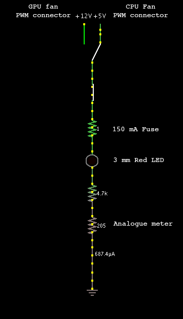
For some reason I need a diode in the circuit for the GPU fan PWM pin not to drop in voltage when connected, if someone could tell me why this is so I would be glad. This phenomenon does not occur with the CPU fan. The 4.7K resistor is chosen empirically by virtue of giving the best “gain” on the meter, i.e. 10% fan speed ~ 10 % meter response, and 100% fan speed ~ 95 % meter response. The gfx card is a EAH6870 DC/2DI2S/1GD5.
I still don’t know why the diode is necessary. Could it be related to the galvanometer inducing a backwards current when it relaxes during the PWM OFF cycle? Contact me if you have any ideas I’m still curious.
Update 2: Let’s start cutting.
originally posted 2011-06-25
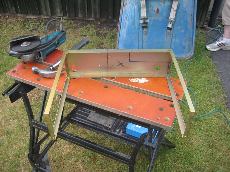
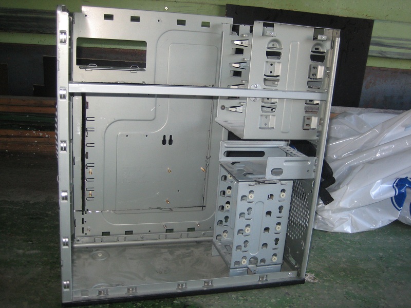
Everything is now disassembled, documented and measured out. I decided to use the I/O backpanel and motherboard mount panel from my old case.
My father-in-law helped me with the manstuff (areas marked with X’s are meant for removal in steel worker culture) :
The PSU (OCZ ModXstream Pro 600W) also needs some grinder action to fit:
Old case:
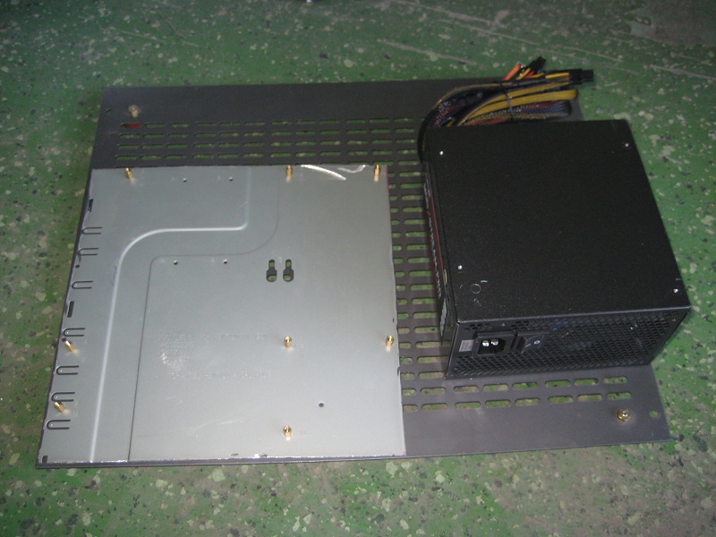
MB mount panel transplant, PSU and bottom of VOLT case:
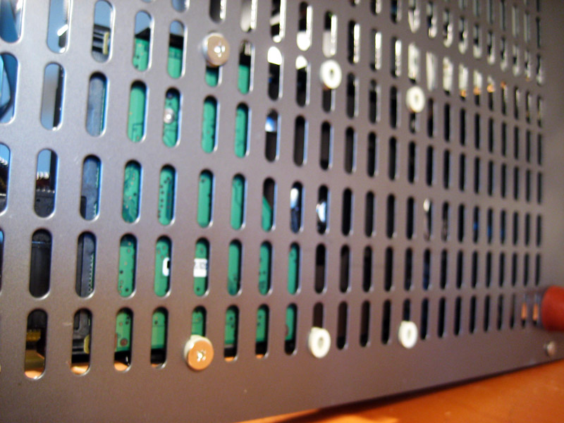
If you do this:
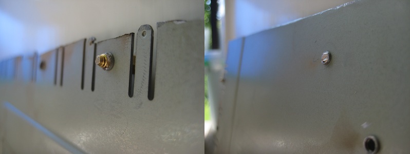
Stuff will fit this well:
 What fits this well? I’m guessing the picture shows the under side of the mother board (MB) mount panel, where the ends of the screws were keeping the panel from lying directly on top of the bottom of the VOLT case.
Next up, repairing the old switches and raising the front panel. Now back to soldering.
Again, please take care to show sharper pictures and to post process them a bit. Also, more descriptive captions would be helpful.
Update 3: Bitches don’t know about my switches.
originally posted 2011-06-27
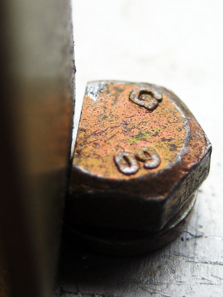
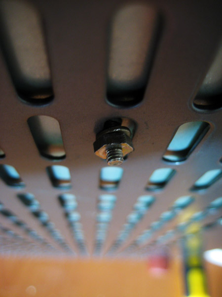
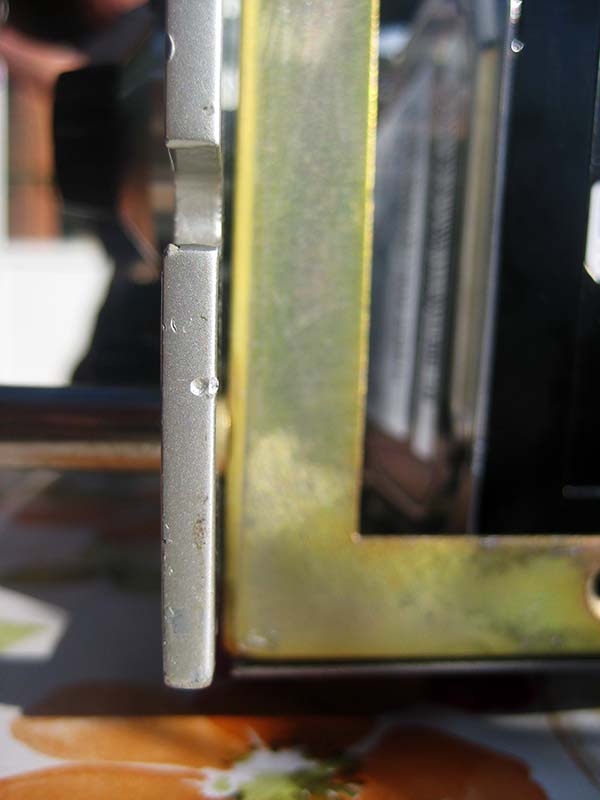
The VOLT case was exaxtly 120 mm in height, which is a just a little to shallow to accommodate the gfx card. Therefore, me and my father-in-law raised the front panel about 30 mm by drilling a new hole in the frame and cutting the upper bolt.
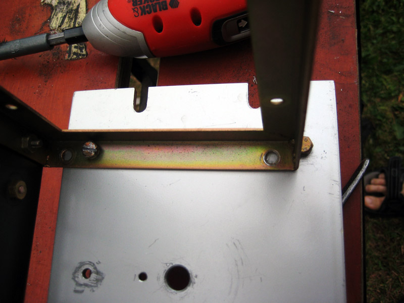
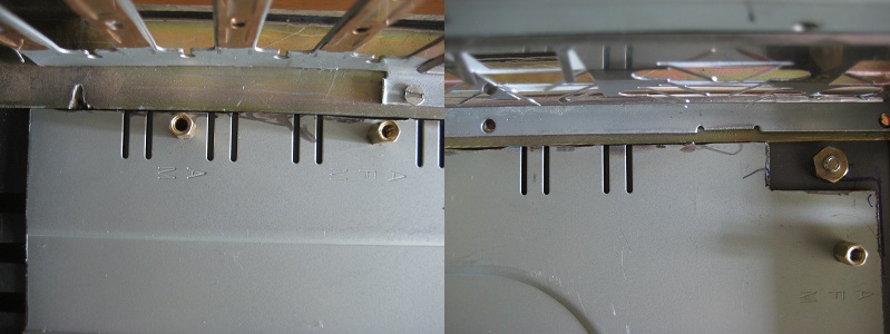
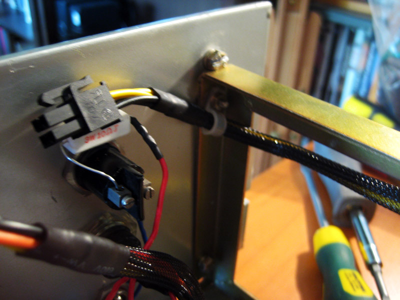
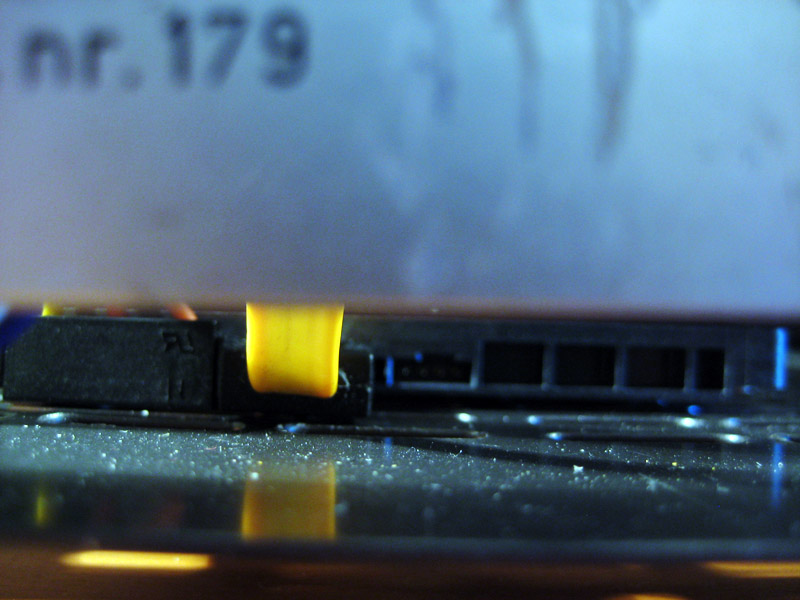
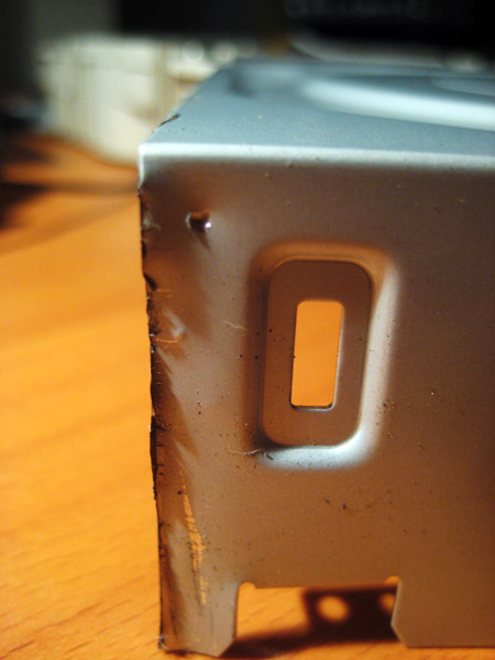
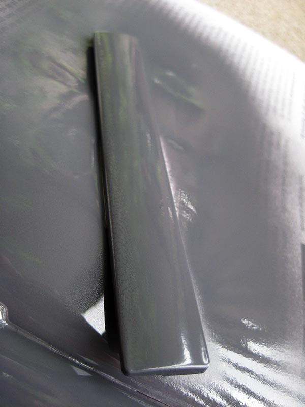
Upper front panel fastening bolt:
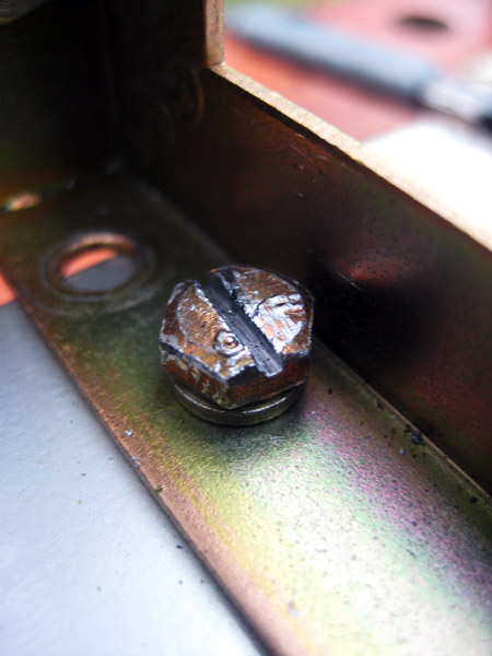
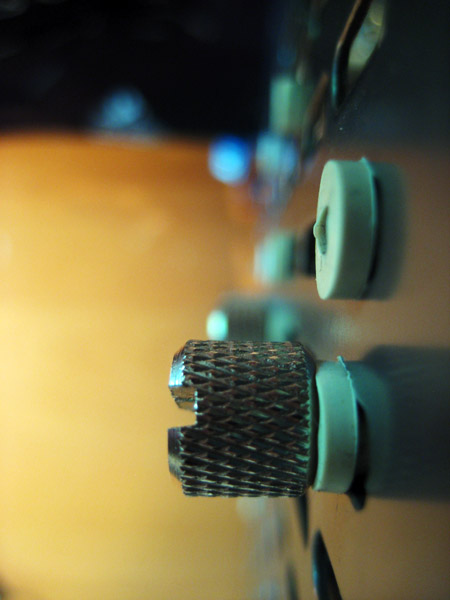
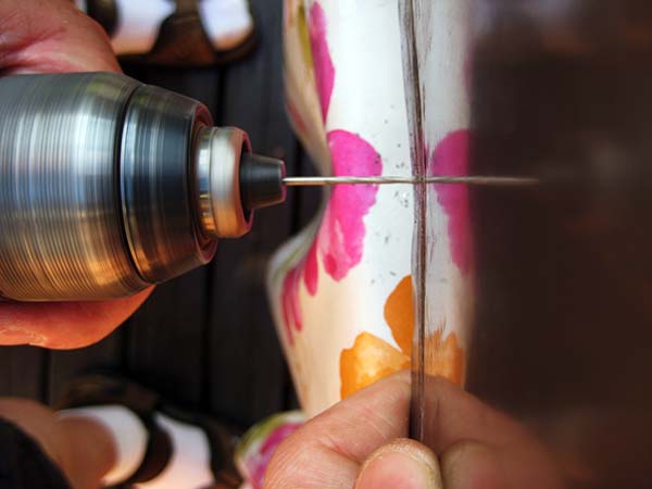
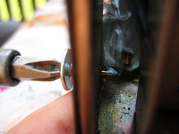
Also my father-in-law, being a man of great practical knowledge, decided to grind grooves into the lower bolts so that the front panel could be removed with a screwdriver. This turned out to be immensely functional down the road.
Besides being painfully obsolete, the VOLT case also had several broken switches, so I can easily see why it was kicked to the curb.
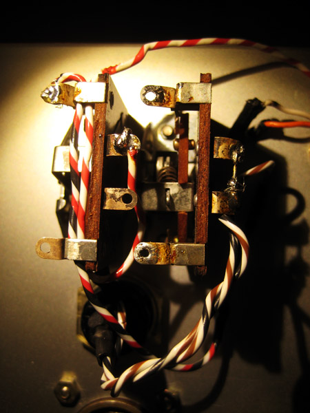
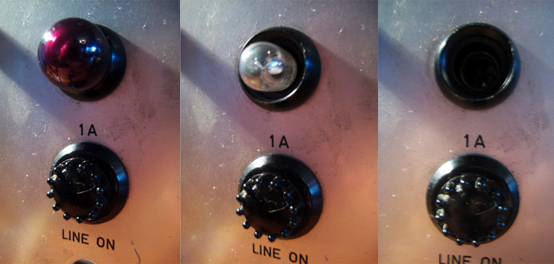
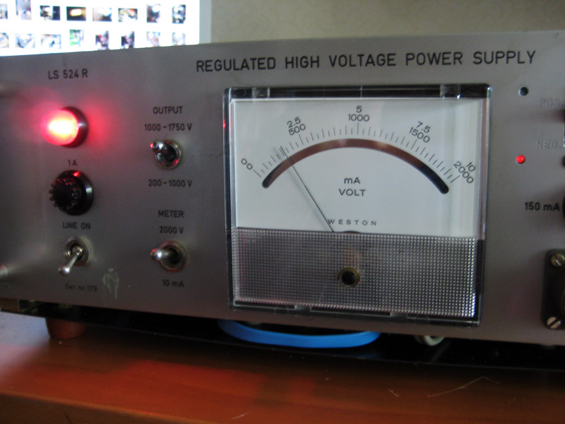
Here is a close-up of the left hand side of the front panel that is going to be the system indicator light circuit (see update 1):
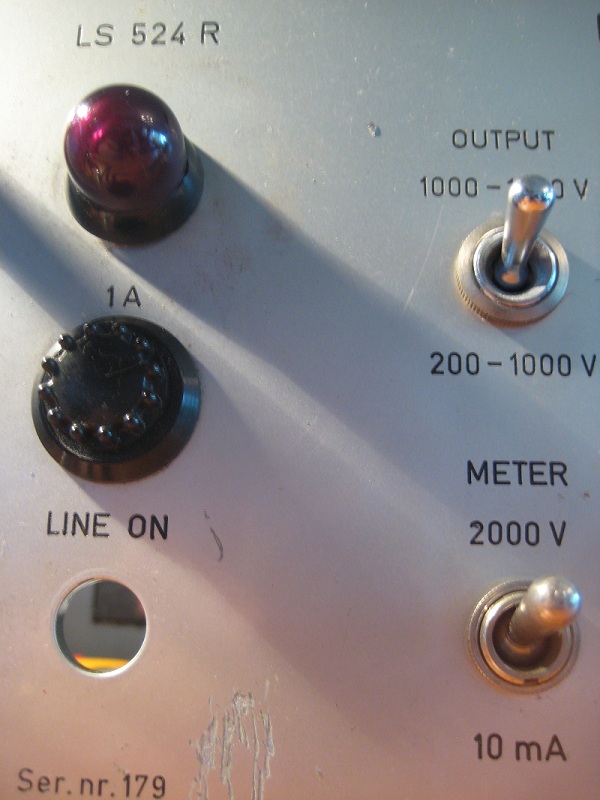
The METER 2000V/10mA switch in the lower right corner was stuck in 2000V mode, so I removed it.
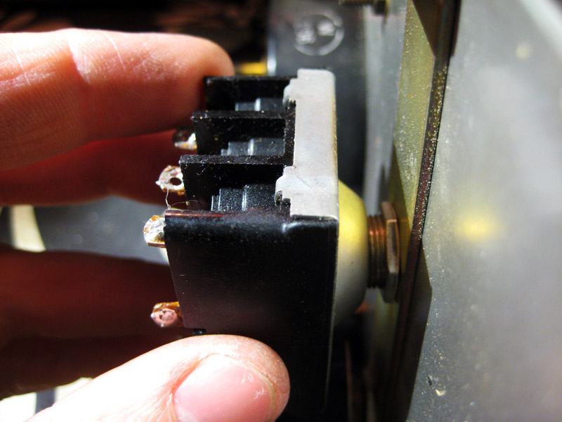
…and had a look inside.
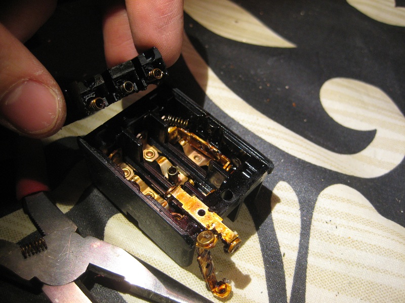
It took some tinkering, but finally it was fixed.
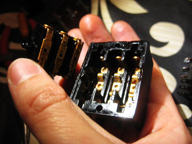
All done.
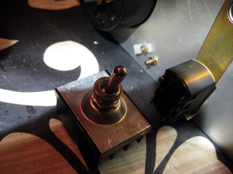
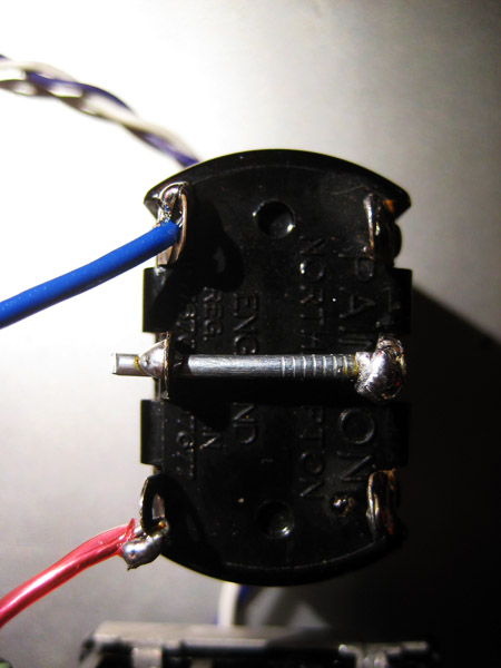
On the right hand side we have an other type of switch, this one will be the ON/OFF switch for the analogue meter circuit (the CPU/GPU switch is identical, but with the connecting studs in alternating holes).
Next up, outputs are turned into inputs and the ON/OFF switch.
Pictures are improving, but still unsharp and poorly captioned. However, I really enjoyed the .gif of the analogue meter switch at the end.
Update 4: A bit of the old in&out, on&off action.
originally posted 2011-06-27
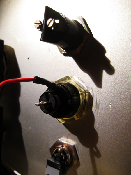
While playing around at the beginning of the project, I accidentally broke the LINE ON switch so that the flick (?) and the threaded cylinder came loose from the switch itself. This turned out to be serendipitous, since I now could use the push switch from my old case after some slight modifications of both switches.
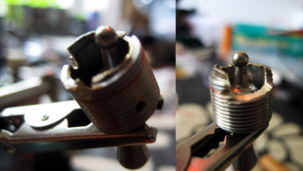
Testing the switch.
I don’t think I would have solved the system power switch problem with a constant switch anyway, since the MB wants a transient signal to get going (or turn off). Had I used the original switch in its unaltered condition I would have had to flick in on/off really quickly at every system boot, this now is accomplished automatically by the trusty old push switch.
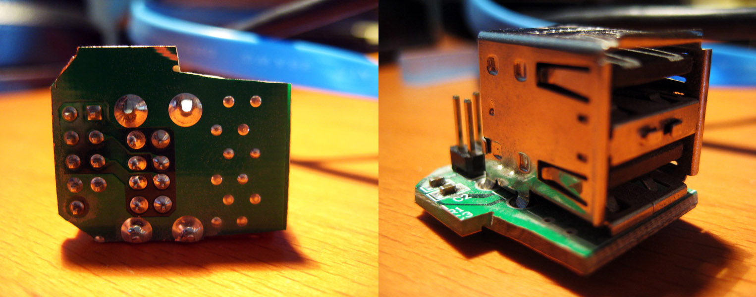
I decided to try and fit two USB ports into the old DC power output (bottom right next to meter in post 1). I started with the old front panel PCB carrying the audio/USB connectors from my old case and a Dremel (knock-off).
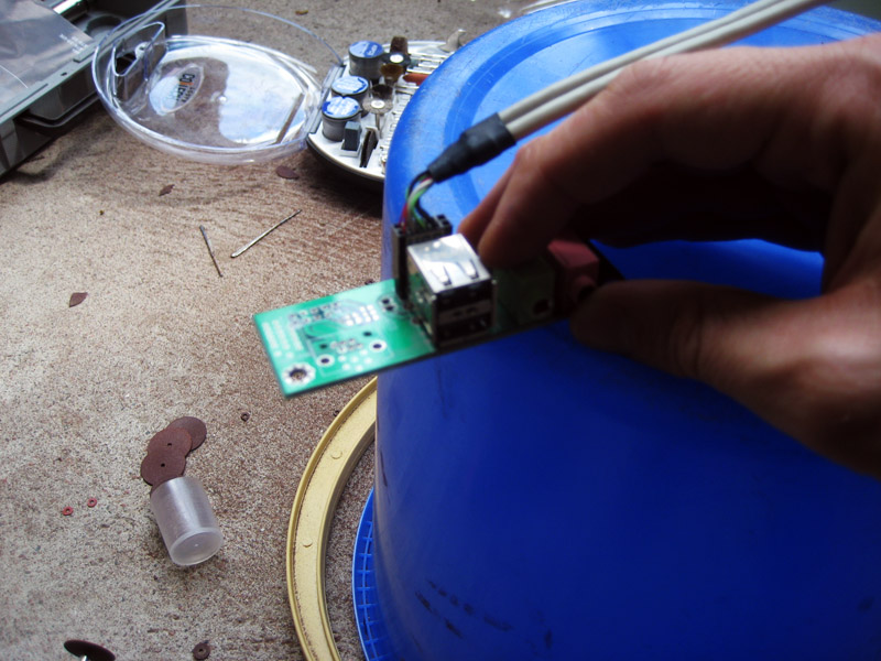
And finished with this.
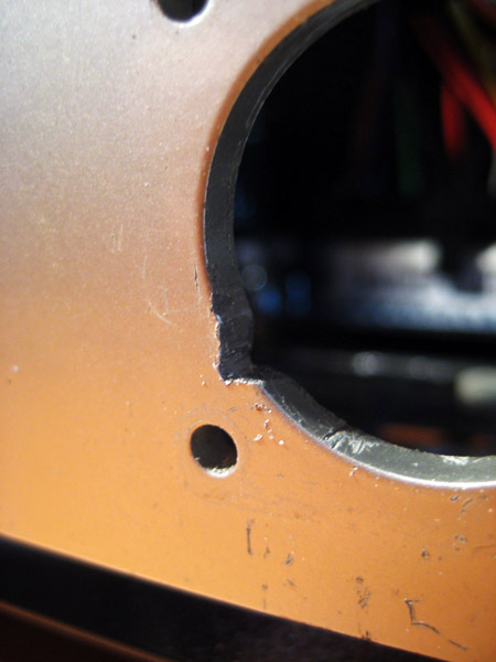
After some grinding on the outlet everything fit really nicely, here is the result compared to the identical back panel inlet.
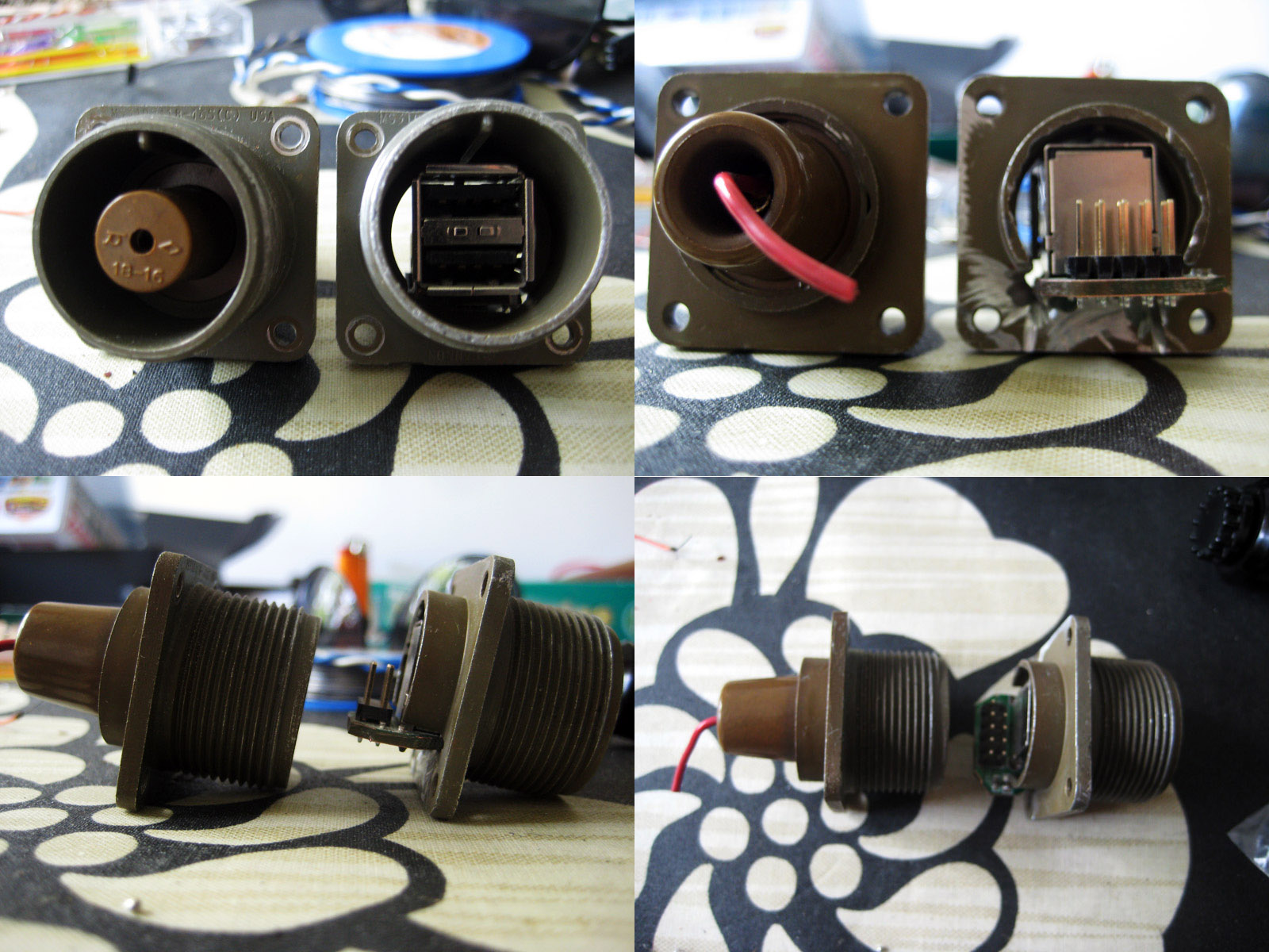
The VOLT case front panel itself had to be modified slightly to ensure a snug fit of the USB port board.
My Dremel knock-off had died on me at this point so I had to change to a different file system.
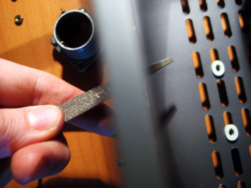
I always appreciate a good hand job.
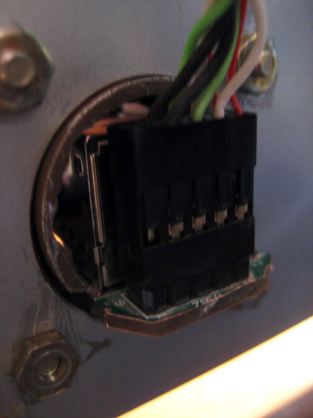
View from the back, after mounting.
And most importantly, it works!
That’s it for now, next update will be about the need for (fan) speed.
Its good to see that the quality of the pictures is steadily improving. I can report that 3.5 years later, the USB still works like a charm and has not come loose.
Update 5: Analogue is the core of computing
originally posted 2011-06-29
Lets start this post with a quick PSA on how a galvanometer, or analogue current meter works. At it’s heart it is a current going through a coil between the north and south poles of a permanent magnet, the more current you have, the stronger the magnetic field emanating from the coil, the more it’s affected by the magnet, the more the needle moves (Galvanometer wiki).
The front panel galvanometer.
Back of galvanometer, note the date.
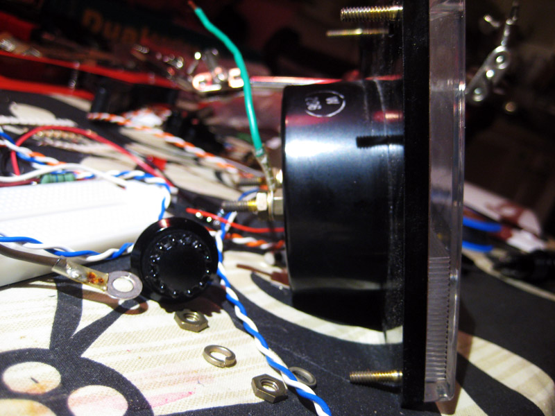
Side view.
One major technical point is that the current going through the galvanometer needs to be very small, in the order of ≈ 500 µA, or 0.5 mA (depending on the type). My plan was to connect the galvanometer to the PWM connectors of both the CPU and GPU fans, I calculated that I would need a 10 kOHM resistor if the circuit maxes out at 12V. Being an experimentalist I spent a lot of time optimizing the resistor choice, and finally settled for 4.7K, which worked for both the CPU and GPU if I added a diode to the circuit. If I did not include a diode the GPU fan would be stuck in low rpm mode, which I do not understand. The schematics are in update 1 if someone could explain this I would be most grateful.
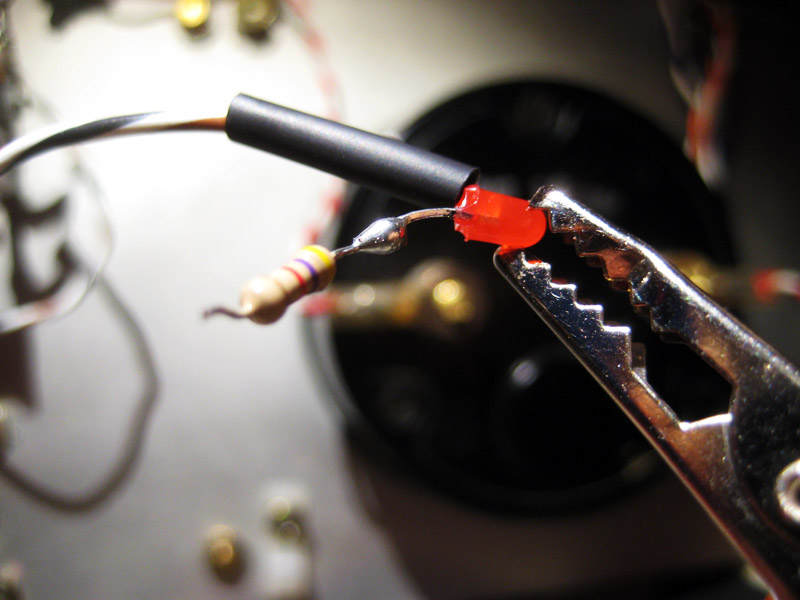
Again serendipity struck, because I had two 3 mm screw holes in the front that I did not know what to do with, so one got the PWM/galvanometer circuit diode, now swapped to a 3mm red LED, and the other got the HDD read/write diode from the MB, also swapped for a 3mm green LED. Even though I said no LEDs at the start, I feel that the dim red&green ones are in artistic harmony with the general build, also I noticed that since the SSD is silent it adds a useful function.
Front panel with diodes mounted in screw holes.
Both LEDs had to (carefully) be filed down at the base for a snug fit, the 4.7 K resistor is also shown.
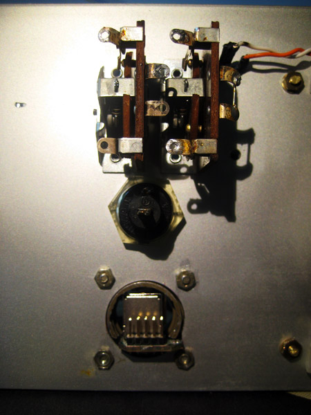
Here is the back side of the switches, fuse, and USB ports, before wiring. You can also see the HDD indicator LED in the upper right corner.
Now on to the wiring, all wires were recycled from the original guts. The PWM pin is the fourth (blue) wire on a 4-pin fan connector.
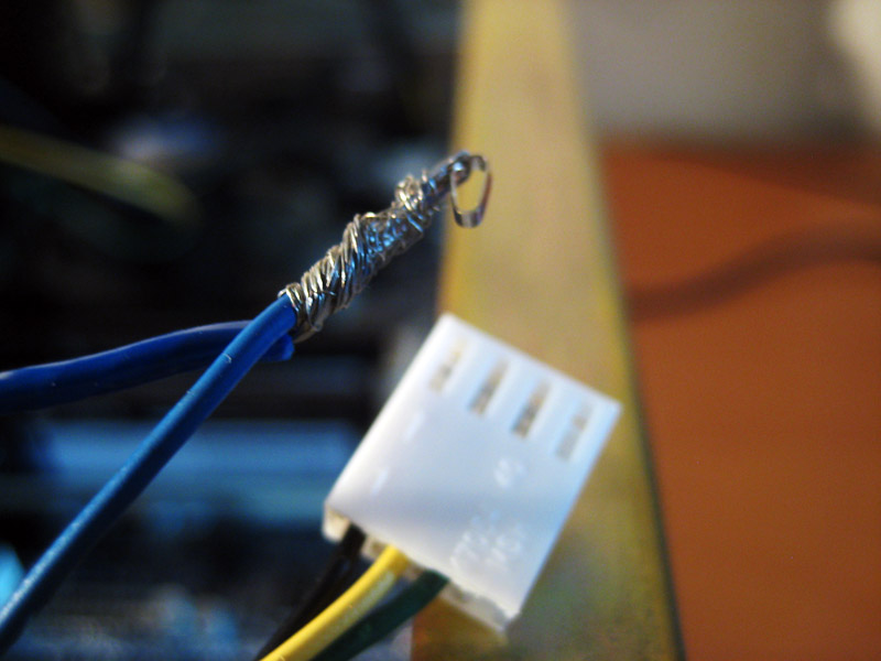
Here is a close up of my GPU fan connector before…
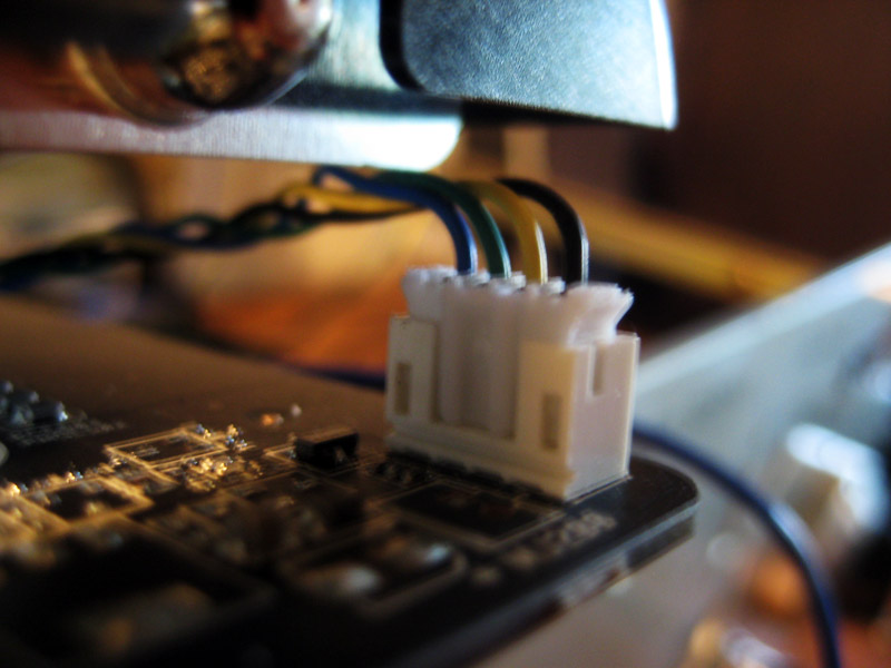
…during…
…and after addition of the parallel galvanometer wire (striped white/blue/black)
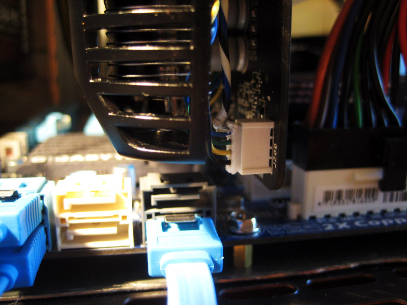
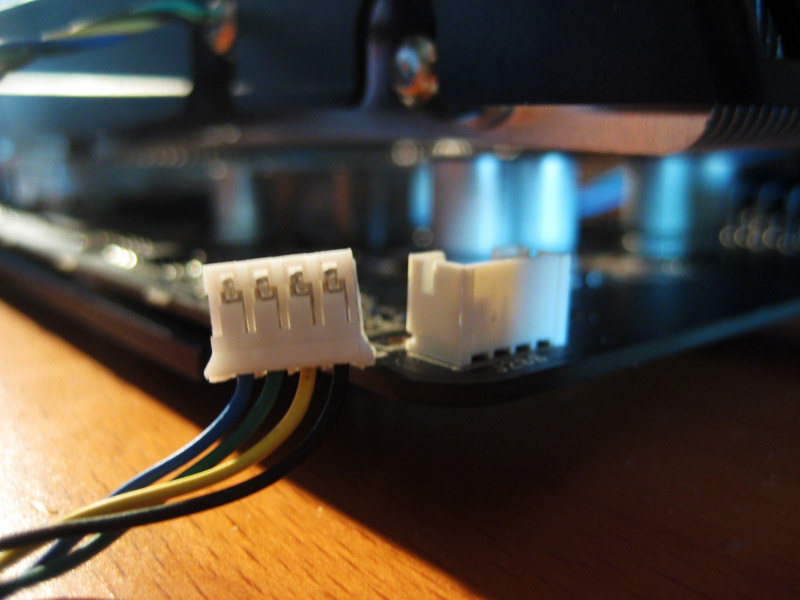
The same maneuver was performed for the CPU fan connector, this time I used blue wire so I could tell them apart when soldering the switch.
Back in place.
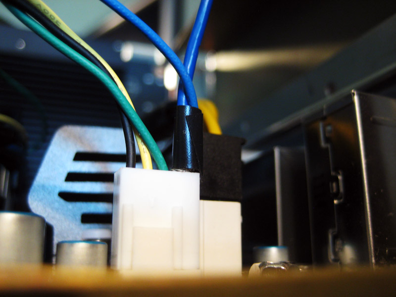
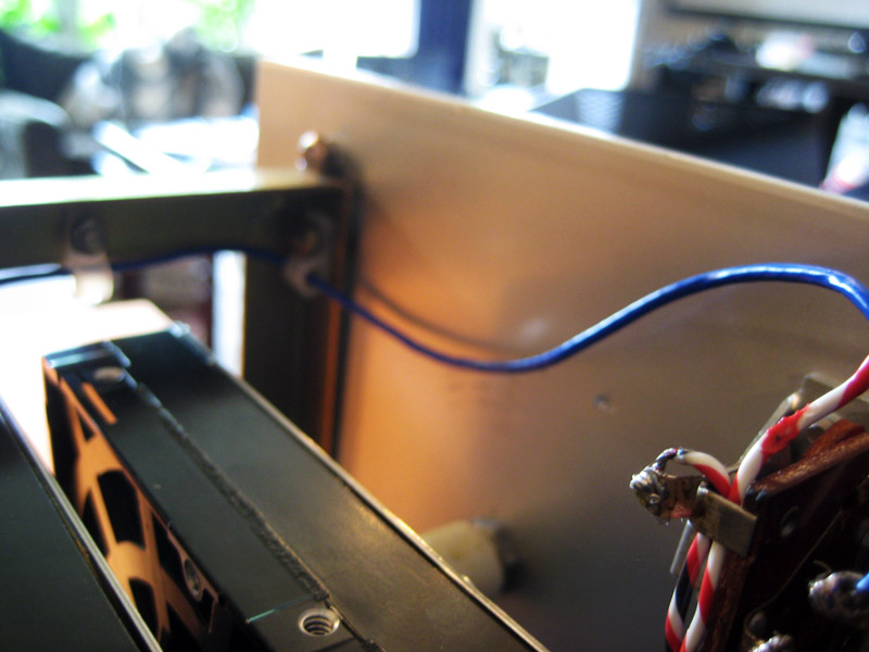
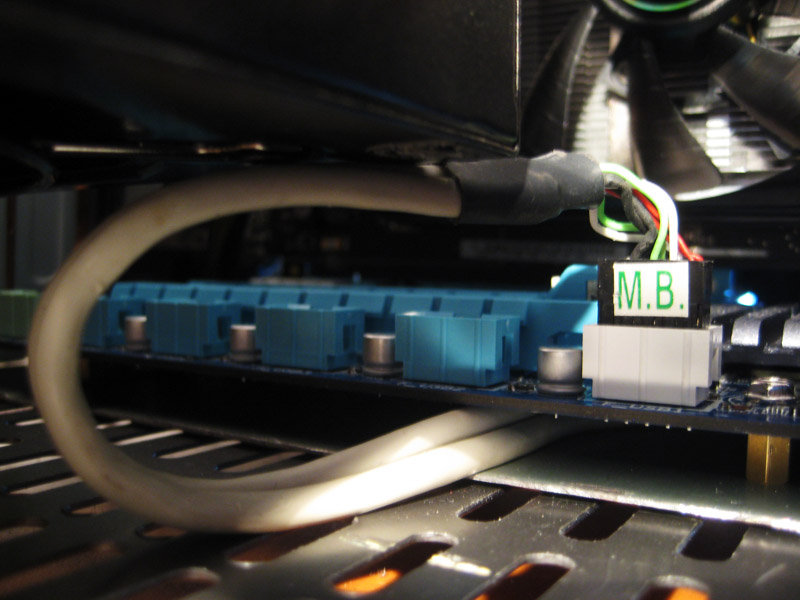
Side view of the case, note the routing of the blue PWM wire from the CPU fan connector, through the plastic cable loops, to the front panel. Plus a sneak peek at the storage HDDs.
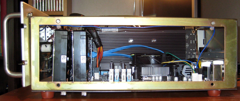
View from the opposite side.
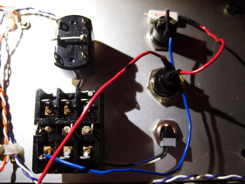
And finally it finds its home at the POS/NEG selector switch. The striped GPU fan wire connects at the bottom of the switch.
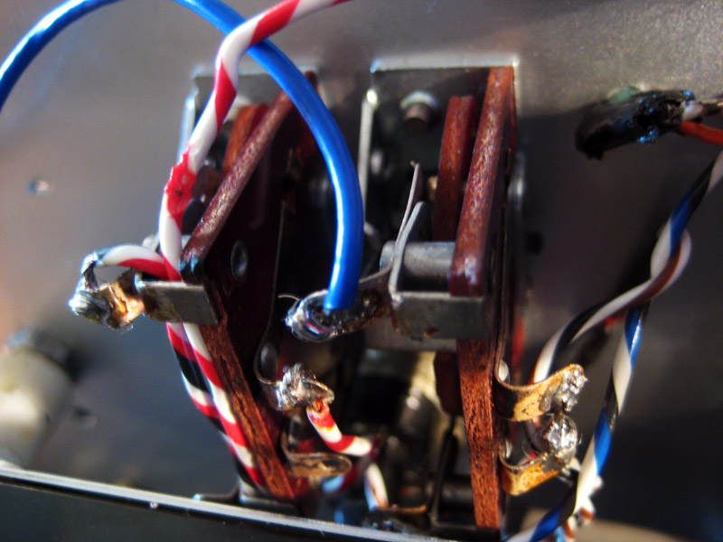
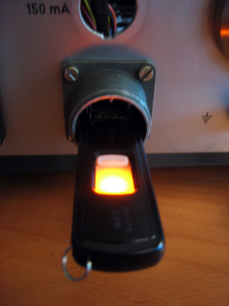
From the POS/NEG, i.e. CPU/GPU, switch the current goes through the 150 mA fuse (striped brown/white/black wire).
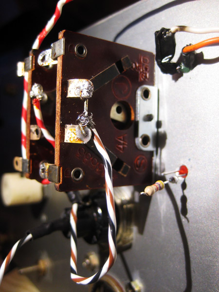
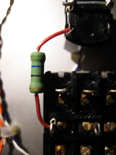
From the fuse the current flows through the LED, the 4.7K resistor, and to the ON/OFF switch (red/white/black wire).
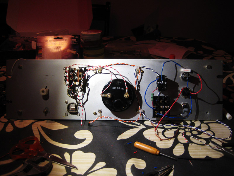
From the ON/OFF switch the current goes through the galvanometer and into a unused Ground connector from the PSU (red/white wire). You also get an overview of the entire front panel backside. On the rigth hand side the system on/off switch wiring is visible.
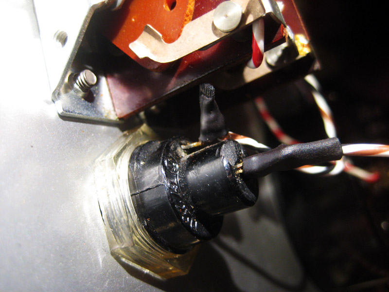
Functional ON/OFF switch in action.
That’s it for now, next time we will be blinded by the light, peace!
Again, improving with the pictures, but its a little hard to follow the whole fan/PWM cable routing thing.
Update 6: The light at the end of the tunnel
originally posted 2011-06-30
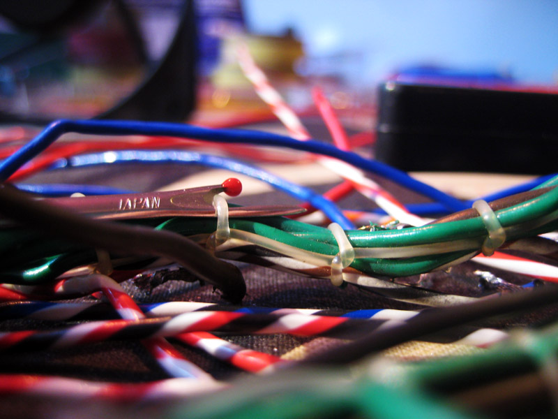
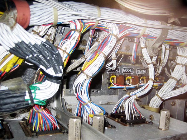
As I wrote in the previous update all the wires I have been using were recycled from the original parts and I just wanted to start this post by showing some true 60-ties cable management porn (before I went at it with a seam ripper). The engineers at Oltronix really took pride in their work, either that or zip ties hadn’t been invented yet.
I am seriously considering ripping up the black plastic cable management web currently on the OCZ ModXstream PSU power cables, in favour of hand binding them with similar nylon rope. What do you think, is this just too much OCD? Hell no, just do it! My grandfather once told me this: “People are never going to ask you how long it took to make, they will only see how well its made.”
Now on to the business at hand, the analogue system indicator light circuit. The light is a 10V/200mA Philips 10mm light bulb underneath a red plastic dome.
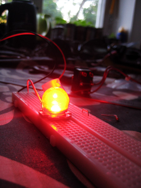
In the beginning I played around with the idea of swapping the light bulb for a red CREE LED that I had lying around, but after testing I realized my folly, it was way too bright and not ‘warm’ enough.
CREE LED test. That actually looks pretty good on the picture, but it was really too bright as I recall.
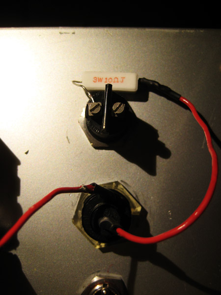
Now to the wiring, the order of the components do not exactly match the circuit diagram in update 1, but who cares. The first red wire, which connects to a 12V pin coming from the PSU goes in to the 1A fuse.
From the fuse the current goes on to a 10 Ohm 3W resistor and in to the lamp (remember, the lamp is rated for 10V so the resistor mellows out the voltage from the PSU).
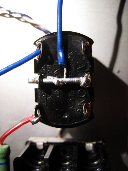
From the lamp the electrons travel through a fashionable blue wire into the circuit on/off switch (originally METER 2000V/10mA switch). Actually, the electrons travel in the opposite direction to the current (minus to plus).
From the circuit on/off switch there are two possible paths:
A) The ‘Dim’ current path, through a red wire and a 56 Ohm resistor (does anyone recognize where I have scavenged it from?). I know, Iknow, from a 12” chassis fan speed selector adapter!”
B) The ‘Bright’ current path goes through the blue wire.

Current paths converge at the two poles of the bright/dim selector switch (originally the OUTPUT 1000-1750V/200-1000V selector switch).
Finally the current goes out through a bridging nail into the PSU ground. This solder joint did not pass the test of time. You really should have drenched that sucker in flux before soldering.
The PSU had an extra 4-pin 12V cable bundle that was unused and not part of the modular cable system, i.e. I was stuck with it in the case, so I routed it so it supplies the lamp circuit current. Here you can also see what the hell I mean by “black plastic cable management web”, since it shows on the cable bundles.
To recap, I started with this.
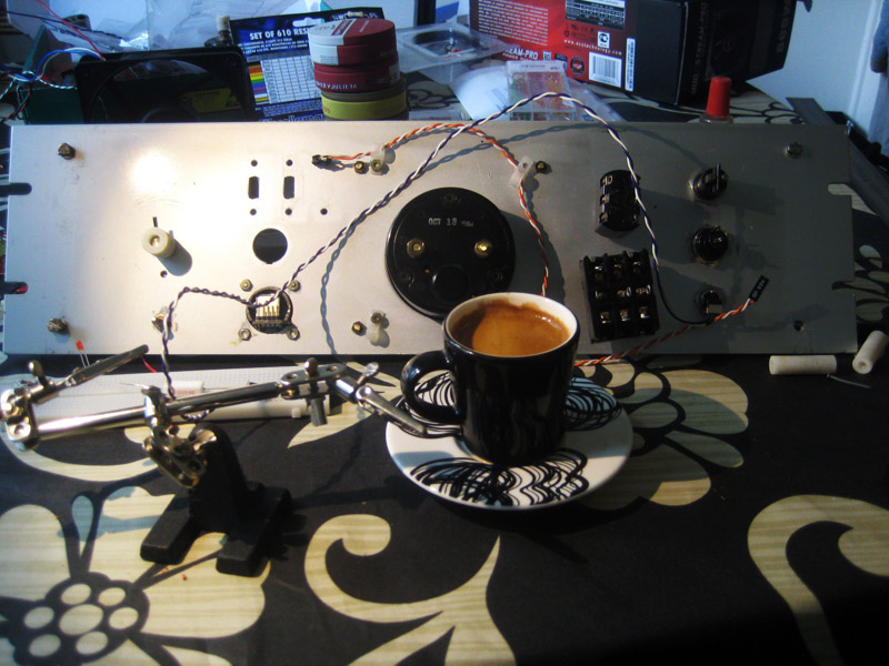
And ended up with this. This is the finished front panel, except for the PWM fan wires, which attach from the MB.
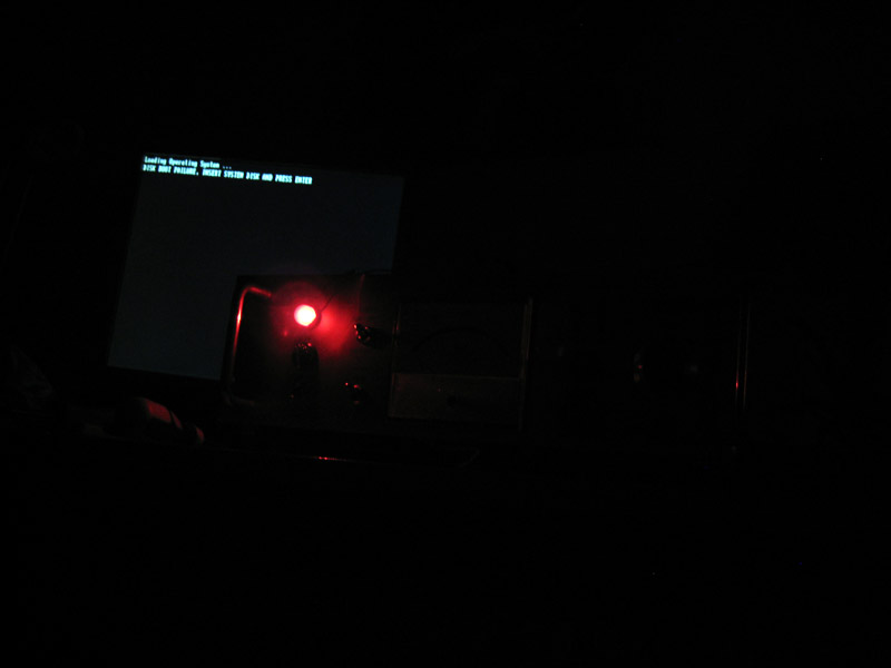
First boot with everything functional.
With the lights on.
Close-up showing the galvanometer and red LED displaying a comfortable low CPU load.
That concludes this update, next up we’ll be going through the actual computer, peace!
Well done on the captioning and most of the pictures. However, some are still unsharp.
Update 7: No Guts, No Glory.
originally posted 2011-07-02
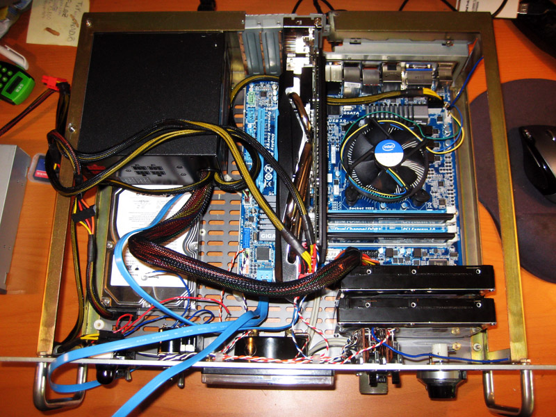
In this update I’ll describe the layout of the actual computer components in the VOLT case.
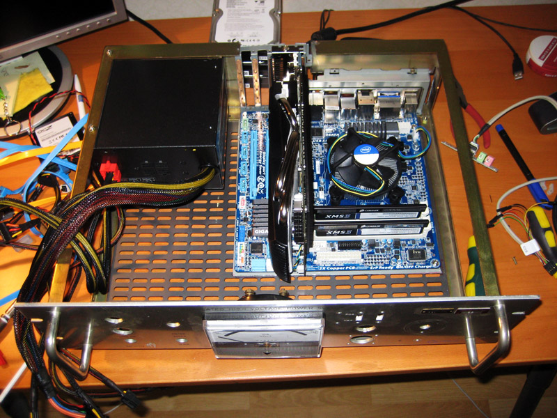
This is what it looked like when I had finished the grinder work and fitted the MB mounting plate, the I/O back plate, and the PSU.
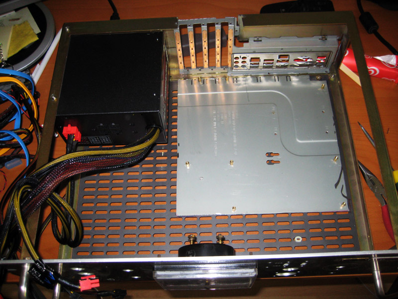
The plate was fastened to the bottom of the case with recycled bolts and nuts.
Then it was the gfx cards and MB’s turn.
Unfortunately I had made a slight miscalculation, so in order to properly fit the gfx card it had to receive a 1 mm shave from the Dremel.
My dedicated Linux disk was fitted first, on the left hand side by the PSU.
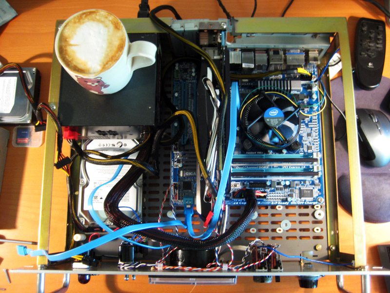
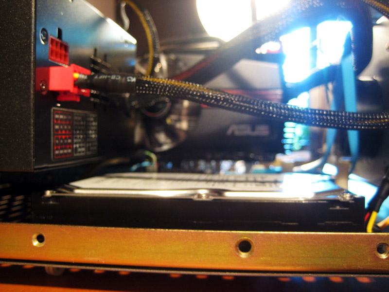
Then I fitted the 2TB HDDs harboring the RAID 1 storage array, as seen to the right.
The SSD housing win7 is squeezed in in front of the RAID array.
The HDDs are resting on standard rubber grommets that fit really nicely into the holes of the case bottom.
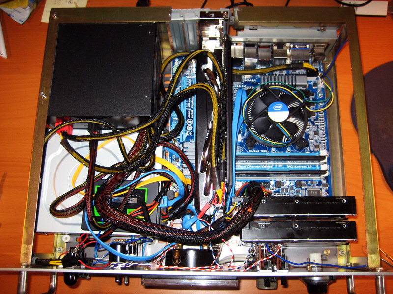
View from top, where the front panel USB cable also is seen going in underneath the MB…
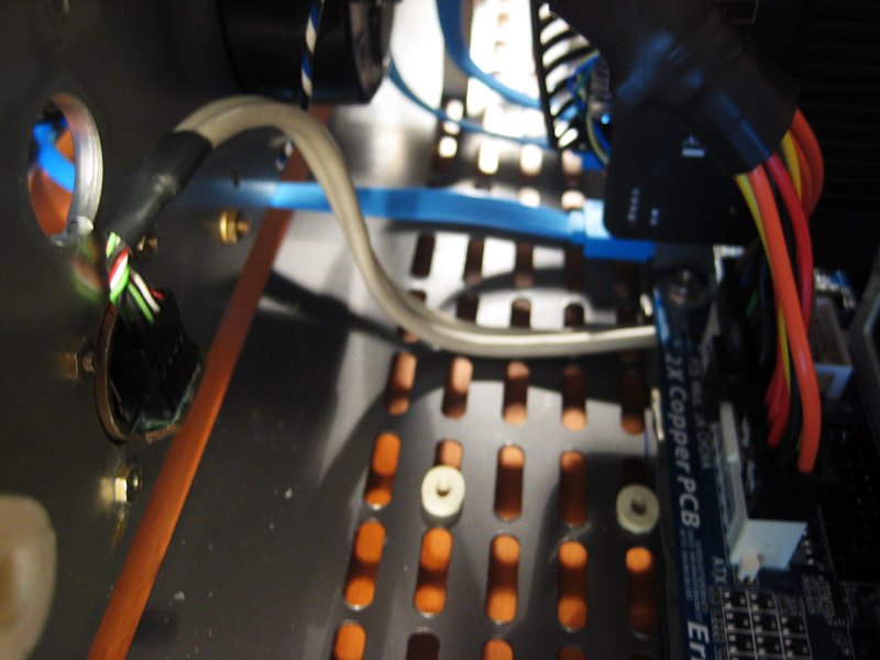
..and out where it belongs.
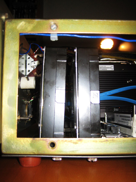
Bottom of RAID array, as seen from the front…
…and side
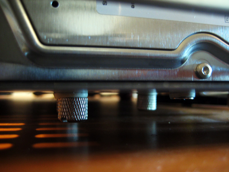
The Linux drive, as seen from the side.
…and underneath, unfortunately I ran out of fancy thumb screws.
There really isn’t much clearance for the cables on the Linux disk, but the grommets make it work.
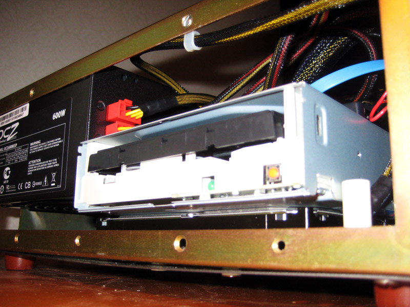
I put the Blue-ray player on top of the Linux disk with the tray facing towards the left. The cables sure are adding up.
In the end the components fit really nicely. I’ll end with some zoomed out shots of the right…
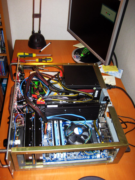
…and left sides.
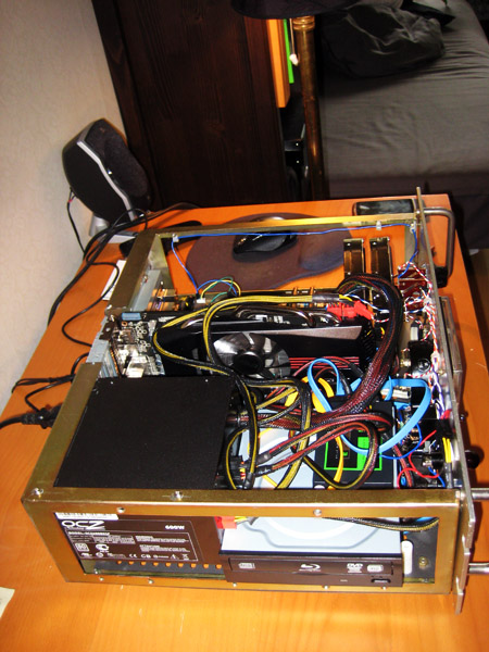
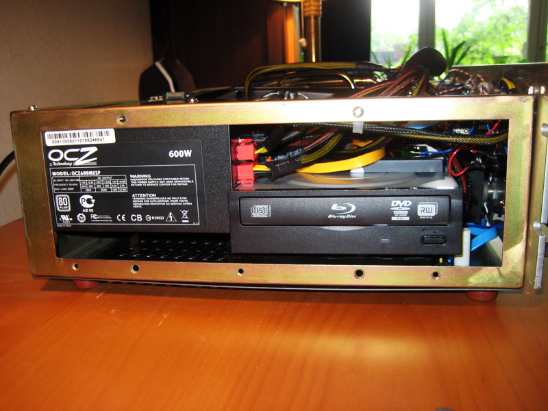
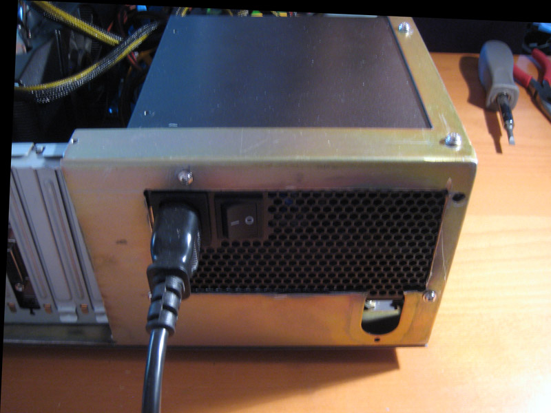
And before I forget, the back side…
PSU.
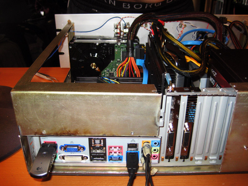
I/O panel (disregard background). Why would you call attention to that?!
That’s it, next (and possibly final) update will be about cutting a hole for the Blue-ray tray and fitting the case fan.
RAID-ing two “ecoPower” disks was not a good idea. When they spin down in to power saving mode, the RAID controller detects it as a disk failure and starts repairing the array. In the end I had to turn the power saving features off completely.
Update 8: When Warranties are Voided
originally posted 2011-07-11
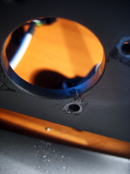
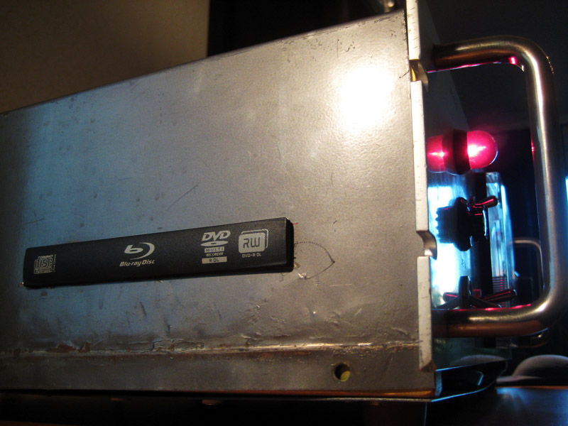
A quick update on fitting of the Blue-ray player and the chassis fan. In order not to intrude too much on the aesthetics of the case, the optical drive was mounted on the left side of the case.
To cut down on the visible plastics I decided to only make a hole for the tray itself.
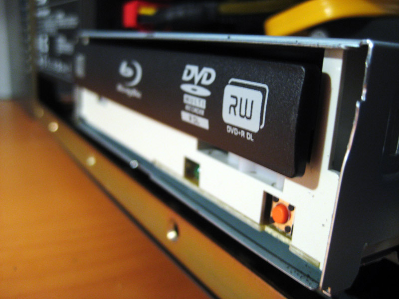
Like so.
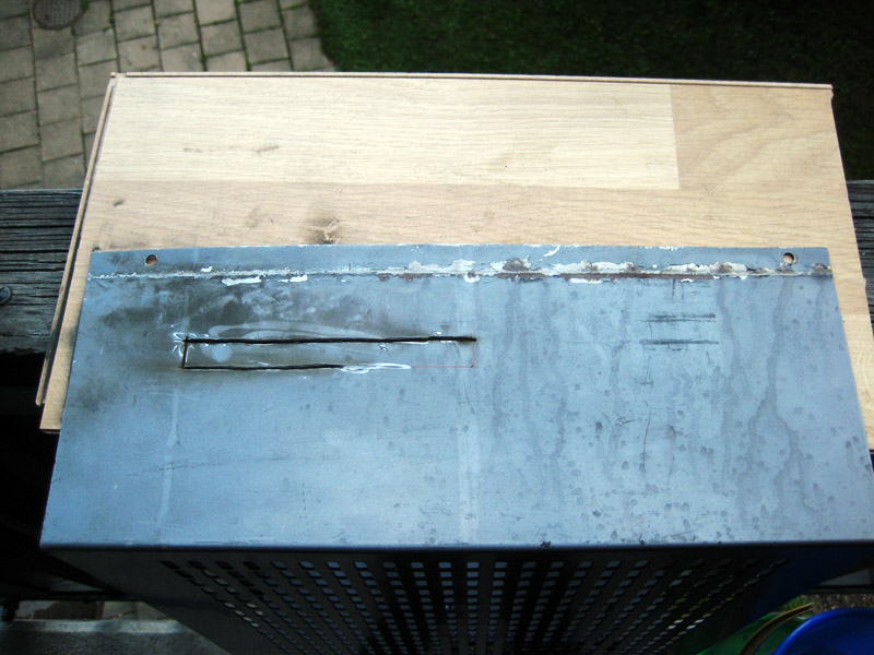
3 Dremel (knockoff) cutting discs later…
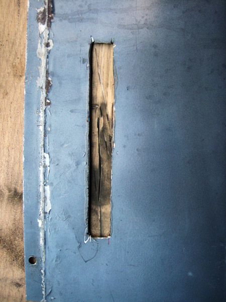
To ensure a perfect fit, both the plastic front panel and the front edges of the Blue-ray player had to be removed, which called for more metal cutting man-action.
Finally it looked like this. As you can see there is no hole for the open/close button, but since it is used so rarely I don’t mind opening and closing from the OS. Maybe I’ll rewire the button to one of the front panel switches later. I was really pleased with how hidden it was by the front panel sticking out, you really can’t see it unless you look for it.
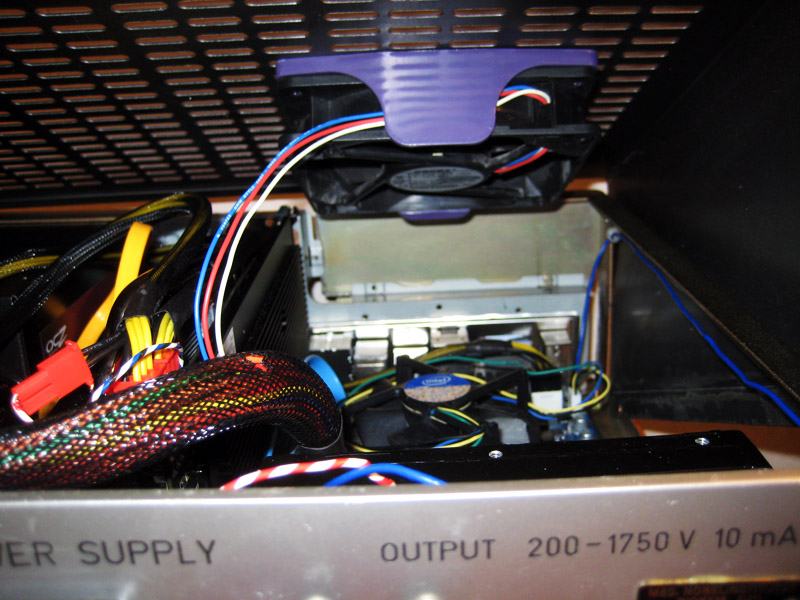
The final component to complete the case was the chassis fan. I reused both the 120 mm fan and its holder from my old case. The holder and fan were mounted in the lid of the case, pushing air down directly above the CPU fan.
Measuring up where to fit the holder.
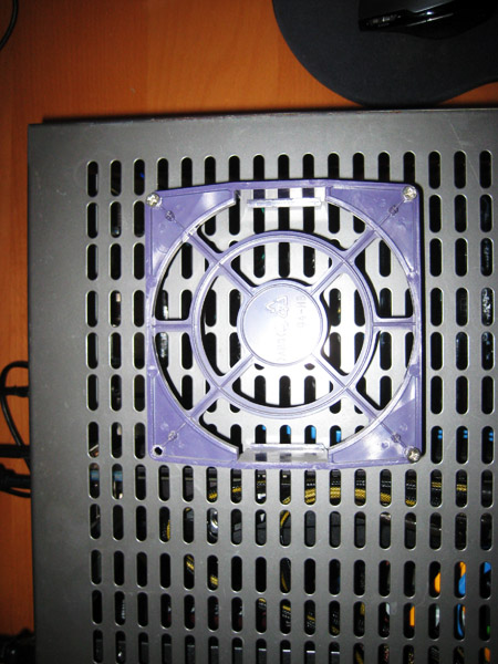
…fitted, mounted and done.
Here’s an overview.
This weekend I’ll finish up by drilling holes into the lid so that it can be properly fastened and popped open quickly in case some house guest wants to have a look inside. I will also be on the lookout for an aluminum ledge to cover the bottom of the front panel with (see bottom of above picture). That gap is still there, I just tidied the cable routing a bit.
If there is general interest I can throw up a video and some work station pics on the whole finished build and its functions, please indicate so in the comments if that is the case. Also never happened.
Peace!
Update 9: Inspiration
originally posted 2011-07-26
A quick vacation update. Me and the wife went to the NASA exhibition at the Museum of Technology in Stockholm. I found some nice examples of old style cable lacing, so I decided to redo all the cables in the VOLT case (next update)
Here are some inspirational shots:
V2 Rocket.
Gemini space craft.
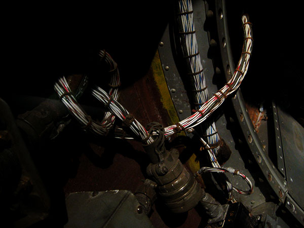
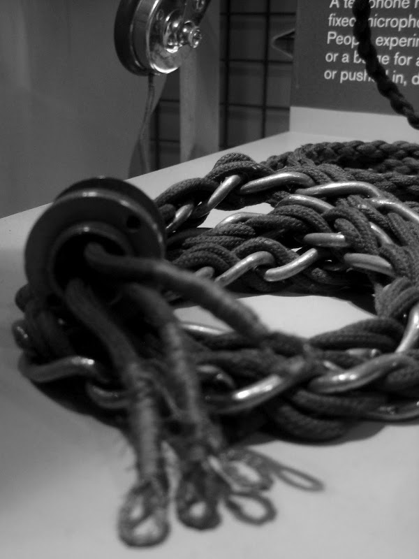
Old Telephone cords.
I also found the link to NASA’s official cable management document with instructions.
Let’s see how this goes…
I never posted the link, but here it is.
Update 10: Finalization
originally posted 2011-07-27
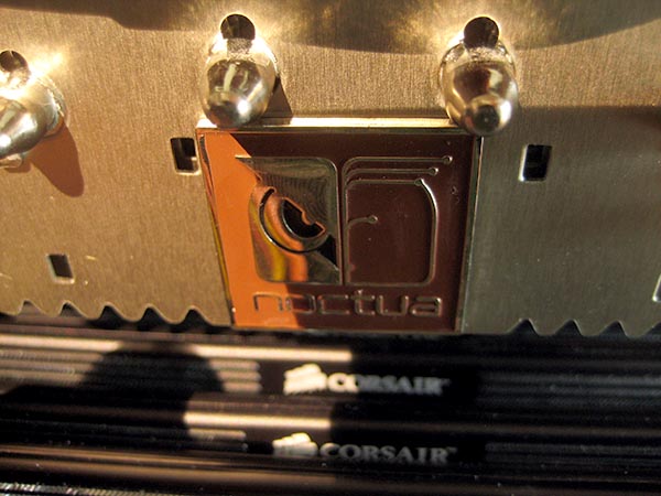
After I started to work on my computer I realized that I needed an additional 8 Gb of RAM. While I had my spending pants on I decided to also splurge on a Noctua NH-C12P CPU cooler.
In order to install everything I had to remove the front panel, which gave me an opportunity to insert washers to straighten up the front panel.
I also drilled holes into the bottom of the outer case so that I could fit thumb screws into them.
Threading the holes.The out of focus tape is there to collect the metal chips from the drilling, since I did this without removing the components (potentially catastrophic, but it went well, score one for laziness).
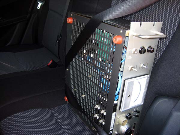
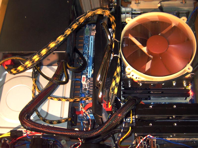
Nobody puts Baby in the back seat…
Close-up of the CPU cooler.
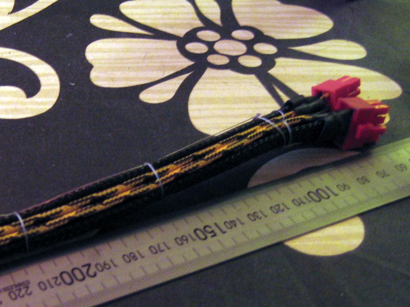
Finally I got to the cable Weaving. This is what the PCI power cables looked like when I started with them.
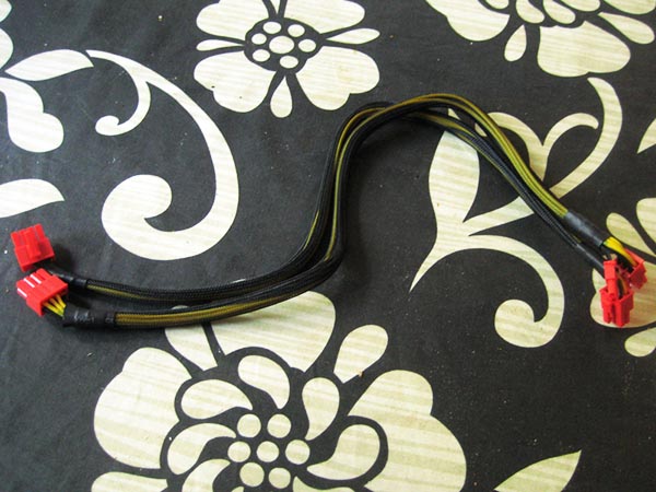
Re-sleeved and cable woven. I used insulated jewellers wire for the weaving.
I also made custom, sleeved and woven SATA power cables.
…and painted the Blue-Ray tray in a more neutral color.
Here’s the final cable managed picture of the guts.
So, I guess that’s it. I think I’ll also post a video when I get around to making it. That also never happened, but I do have a YouTube channel nowadays.
Thanks for reading!
Comments, suggestions, improvements?
/J
Update 10: Exosceletal patchwork
originally posted 2011-08-11
Here is a pic of the front with all the bells and whistles, USB front ports, HDD writing (green LED), CPU running at ~25% (galvanometer position and intensity of red LED), and system lamp in bright mode.
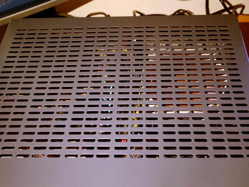
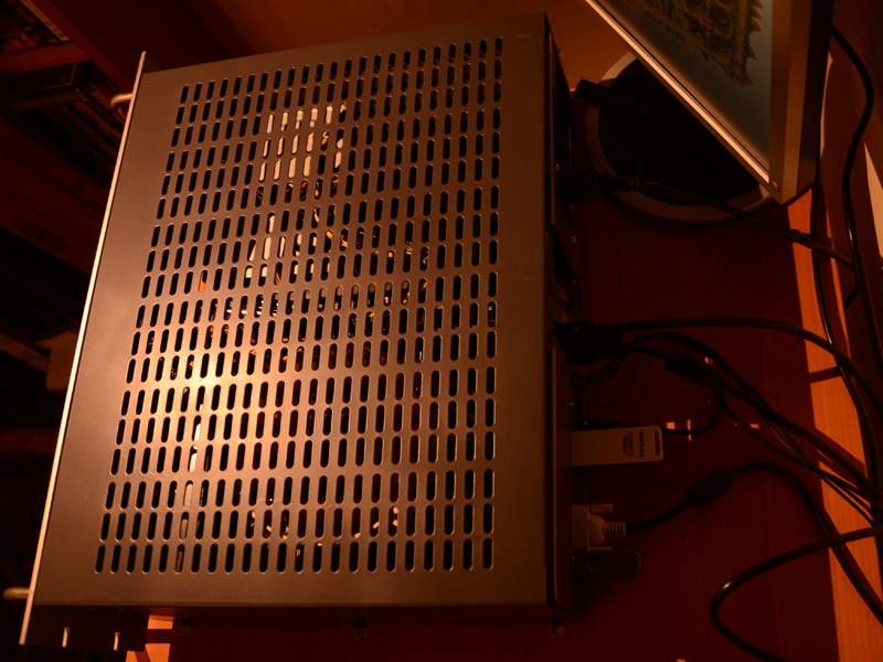
This picture shows the case from the top with a white balance that is more closely matched to the true color of the case.
Pic displaying back side.
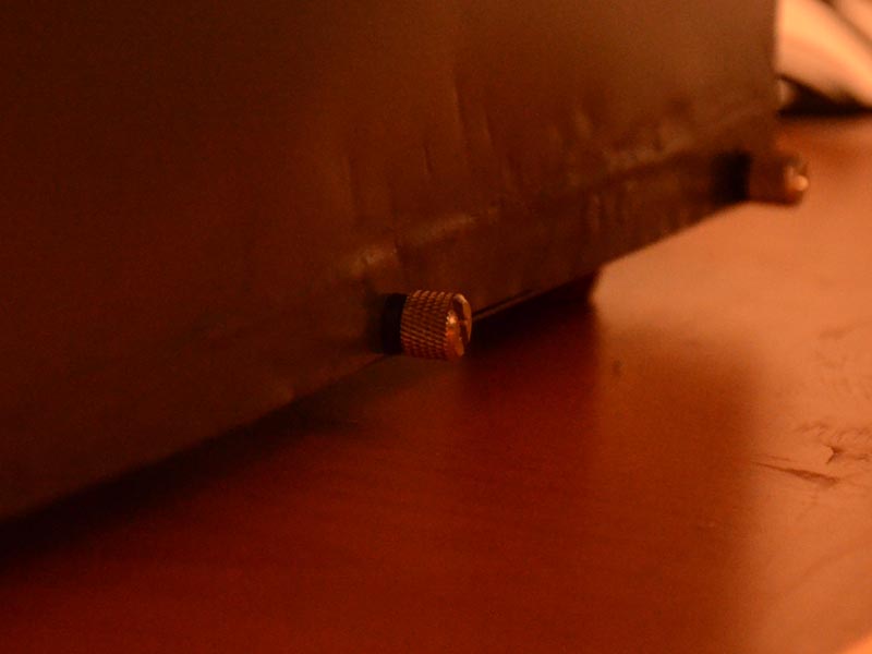
The outer case is fastened with three thumb screws on each side.
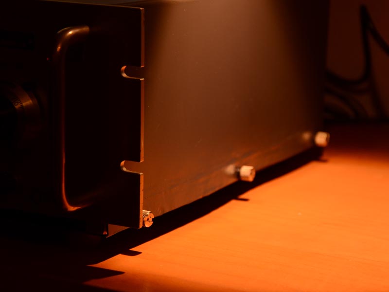
The thumb screws have rubber grommets at the base (for nice as Alan Watts would say).
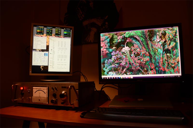
This picture shows VOLT in its natural habitat, with a portrait mode auxiliary display showing benchmarking programs and the main screen rendering a 3D Mandelbulb fractal.
I actually found these frames not to long ago and edited them in to a trippy video. <div class="embed-responsive embed-responsive-4by3"> <iframe class="embed-responsive-item" src="https://www.youtube.com/watch?v=xHBv90N9ULg"></iframe> </div>
Comment Posted by user RedDragon1260:
dude the weaving is awesome, i just plain love this build. Cant wait till you start on the other PSU with the dual meters.
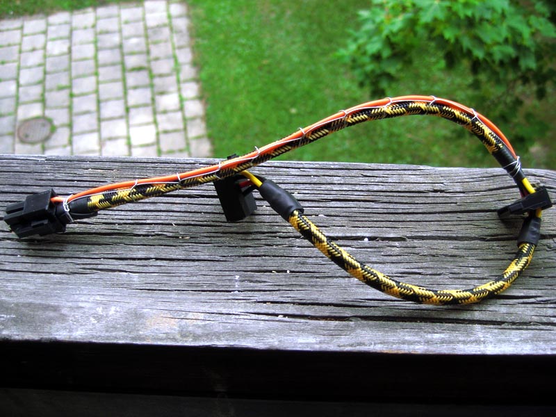
Here is a better shot of the weaving on the PCI power cables.

Now I’m looking for a linear potentiometer that I can connect to the voltage dial, so that I’ll be able to control the CPU fan speed with it. Anyone that has any leads on where to get one. Size is an issue, as you see if you look at earlier posts. Guess what? Never happened, but I do have tons of suitable potentiometers nowadays. The dual meter PSU is still in my book shelf. I haven’t done anything with it because it is still fully functional and I actually use it from time to time.
Peace!
That’s it! I went through it once, fixed the links, did the commenting, now i’m pushing this to GitHub so it goes live. I hope I haven’t made any terrible mistakes.